


3D printed audio plastic shell
2025-05-09Design of Aluminum Alloy Die Casting Mold for Automotive Variable Shell
Variable shell (shell thickness variation) type die-casting parts are high-performance components with complex structures, large differences in wall thickness, and require leakage tests under high pressure. Therefore, defects such as cold shut and gas shrinkage holes that cause leakage during casting need to be avoided or transferred to permitted locations.
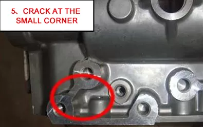
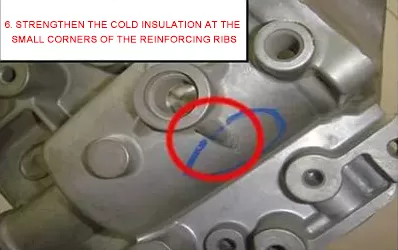
Figure 1 Common Defects in Die Castings
The common defects in die-casting parts are shown in Figure 1, where Figures 1 and 2 belong to the machining allowance problem, which can be solved by increasing the local machining allowance of the casting; Adding an ejector structure on the fixed mold side in Figure 2 can solve the defect problem; The main focus is on analyzing the casting defects in Figures 3, 4, and 5, as well as the improvement measures for the die-casting mold.
Analysis of the original mold structure
Figure 2 (a) shows the layout of variable shell die-casting parts in the original mold, with molten material poured from one side of the part to be formed. From Figure 2 (a), it can be seen that the molten material needs to pass through a 175mm high protruding core to fill the opposite side of the mold cavity. The geometric shape of the opposite side of the mold cavity is relatively complex, with many die-casting islands and blind spots. When the molten material passes through the protruding core area with long distance and large drop, the casting pressure is lost, and it is difficult to ensure the density inside the formed part in the complex cavity area.
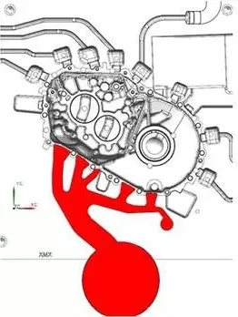
(a) Layout of pressure castings in the original mold
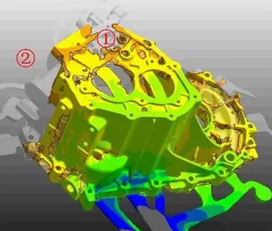
(b) Not fully filled
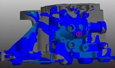
(c) Poor density
Figure 2: Layout of pressure castings in the original mold and defects in the formed parts
Observing the ① area in Figure 2 (b) and the ② area in Figure 2 (c), it is found that there is a problem of incomplete filling and poor density. To solve this problem, it is necessary to add a feeding channel in the lower area opposite the casting to be formed to compensate for the pressure loss of the front melt. If only modifications are made to the original mold scheme, the added sprue will be too long, the pressure loss will also be too high, and there will be too much waste. Therefore, after researching and redesigning new molds, the above-mentioned defect problems can be completely solved.
Optimized pouring scheme design
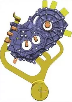
(a) Optimized pouring scheme

(b) Casting simulation filling 20%
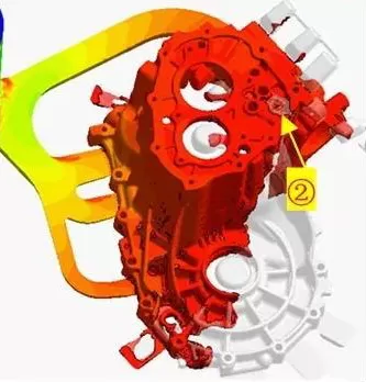
(c) Casting simulation filling 80%
Figure 3 Optimized pouring scheme and CAE casting simulation
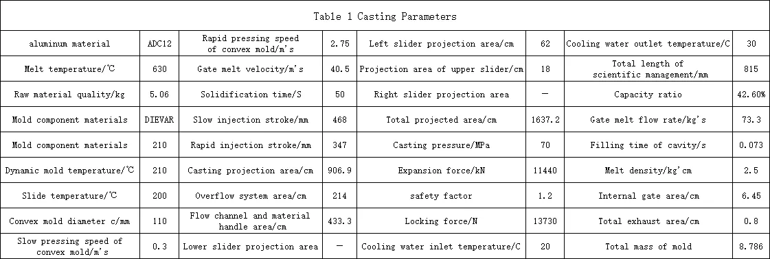
This pouring scheme can solve the casting defects of the original mold and achieve the ideal state. The optimized mold casting parameters are shown in Table 1.
Optimized mold structure design
The dynamic mold structure is shown in Figure 4
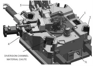
Figure 4 Dynamic Model Structure
1. Positioning block 2. Square guide column friction block 3. Top plate limit travel switch 4. Core quick change pressure plate 5. Sliding block guide column
01. Square guide column friction block
The large die-casting mold (with a mold frame shape of 1500~2000mm) is greatly affected by thermal expansion. When the mold frame temperature is 100 ℃, the axial expansion is 0.12mm. Due to structural shape and other factors, the actual data is about 0.2mm. At the same time, the hole shaped structure of the circular guide column can also cause heat accumulation that cannot be discharged, ultimately leading to local interference fit of the guide column and guide sleeve, making it impossible to open the mold. The use of square guide column structure can effectively avoid the above problems.
02. Diversion channel material chute
The diversion channel is designed with a 5mm × 5mm vertical groove, which utilizes the frictional force generated by the non sloping straight edge to exert a pulling effect on the material handle and sprue solidification, avoiding the risk of the material handle and sprue solidification remaining on the fixed mold side during mold opening, and ensuring smooth withdrawal of the casting during mold opening.
03. Core quick change pressure plate
The back of the core connecting rod is designed with an integral pressure plate, which is fixed on the slider connecting seat. When it is necessary to replace the core during the die-casting production process, all cores can be replaced by disassembling the pressure plate on the die-casting machine, avoiding disassembling the slider and reducing downtime.
04. Sliding block guide column
The sliding block on the mold has a pulling stroke of 200mm. The use of a guide column structure makes the sliding block move more smoothly during pulling, while reducing the weight of the mold and energy consumption.
05. Positioning block
The mold does not have a right slider. To counteract the unilateral force of the left slider, a coarse positioning structure is designed on the right side of the mold frame. The dynamic positioning of the mold mainly relies on the fine positioning structure on the core to avoid repeated positioning.
06. Top plate limit travel switch
To protect the push rod below the slider, a top limit switch and a trigger point have been added to ensure safety, in addition to the existing reset rod.
Fixed model structure 2
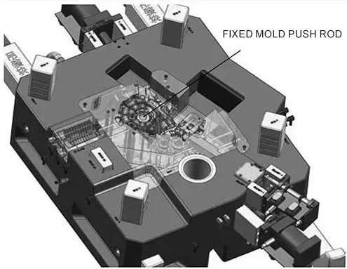
Figure 5 Fixed mold structure
The fixed mold structure is shown in Figure 5. In order to overcome the additional fixed mold clamping force caused by forming complex shaped parts, a push out mechanism on the fixed mold side was designed, including fixed mold push plate, guide column, guide sleeve, reset rod and other structures.
Processing and online measurement system
3. After long-term research and exploration, the current configuration scheme for high-speed machining tool systems is to use a high-precision back pull tool holder with dynamic balance G2.5 within the tool clamping range of ϕ 12~ϕ 4mm, with a tool runout of 0.005~0.008mm, which can meet the high-precision machining of ordinary depths within 18000 revolutions per minute; The special deep cavity processing adopts a heat shrink tool holder scheme, which can meet the small diameter deep cavity processing of 18000 revolutions; The overall tungsten steel anti-seismic tool holder with a diameter of ϕ 16~ϕ 32mm adopts high-precision high-speed and strong tool holder clamping to meet precision machining below 6000 revolutions per minute; This solution is currently the most economical tool matching solution that meets high-precision requirements, reflecting the advantage of cost-effectiveness and having high promotional value.
4. The application of online measurement technology. After the high-speed precision machining of the core is completed, the program automatically calls the probe system in the tool library to automatically detect the machined workpiece according to the program tolerance. Only after meeting the tolerance can the machine be loaded and unloaded from the processing machine and enter the next process. Ensured the quality of "good product upon removal", avoided repeated rework and clamping, and saved testing time.